In two as-built case studies, BIM quantity takeoffs achieved correlations of 95.8% and 99.8% with final quantities, according to the published quantity-estimation study. That's a more useful way to understand BIM modeling than a polished building rendering. The model can be a measurement database, but only when someone has defined, populated, and checked the information inside it.
BIM modeling is the creation of a digital building whose components carry structured information alongside their geometry. A wall isn't merely a shape. It has a type, dimensions, materials, and relationships to other building elements. Those properties let project teams extract quantities, compare designs, identify conflicts, and prepare information for construction and operations.
For a U.S. architecture studio, contractor, or engineering firm, the practical question isn't whether someone can build an attractive model. It's whether another person can use that model for the intended decision without reconstructing the information by hand.
That distinction changes how you scope the work and evaluate remote production support. Start with the deliverable, define what must be reliable, and agree how you'll test it. Software proficiency matters, but a dependable model also requires clear responsibilities, controlled exchanges, and design review by the appropriate professionals.
What BIM Modeling Is and Why Firms Use It
A global study covering nine major markets found that two-thirds of construction companies reported positive returns from their BIM programs, with positive results reported by more than 95% of surveyed firms in Japan, Germany, and France, according to ENR's coverage of the 2014 study. These are historical survey results, not a promise about your next project, but they show why firms evaluate BIM through business outcomes rather than presentation quality alone.
Consider an architect modeling an outpatient clinic. The team places doors as identifiable building components, assigns door types, and connects them to room information. A project manager can then review a door schedule, while an estimator can group doors by type rather than count symbols across separate sheets.
A database with a visual interface
A useful analogy is that a drawing set is a photograph of the design, while a BIM model is closer to a database with a 3D front end. The analogy isn't exact, because drawings contain extensive technical information, but it highlights the difference between reading a representation and querying structured objects.
A duct may carry its dimensions, system assignment, elevation, and connections. A wall may carry its construction type and material layers. These properties allow teams to ask specific questions, provided the modeler has populated the right fields and used consistent conventions.
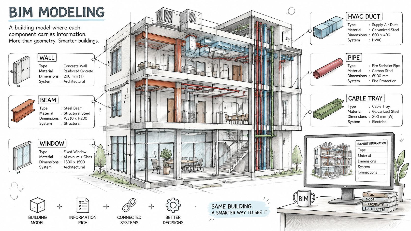
What makes the information useful
BIM isn't a particular software purchase, and teams don't necessarily author everything in a single shared file. Architects, structural engineers, and mechanical, electrical, and plumbing teams may maintain separate discipline models that a coordinator combines for review.
The value depends on whether those teams follow compatible rules. A beautifully modeled door assigned to the wrong category can disappear from a schedule. A duct modeled at the wrong elevation can mislead a coordination meeting.

Practical rule: Ask whether a colleague could extract a correct door count or locate a meaningful duct conflict without asking the author to explain the file.
If the answer is no, the model may still communicate the design visually. It hasn't yet demonstrated that its information is dependable.
The BIM Modeling Process Stage by Stage
BIM modeling tasks and outputs by project stage
| Stage | Modeler's main task | Output handed over |
|---|---|---|
| Setup | Agree naming, units, coordinate system and file structure | BIM execution plan and project template |
| Schematic design | Model massing, spaces and gross areas | Early model for area and cost checks |
| Design development | Model walls, structure and main MEP routes with typed elements | Coordinated design model |
| Construction documents | Tag elements and extract schedules for sheets | Sheet set, schedules and model file |
| Coordination | Federate disciplines, run clash tests and track issues | Issue log with status and owner |
| Procurement and fabrication | Detail assemblies for shop drawings and prefabrication | Shop drawings and fabrication models |
| Construction and handover | Update the model to as-built and attach asset data | As-built model and handover data |
Establish the project rules before authoring
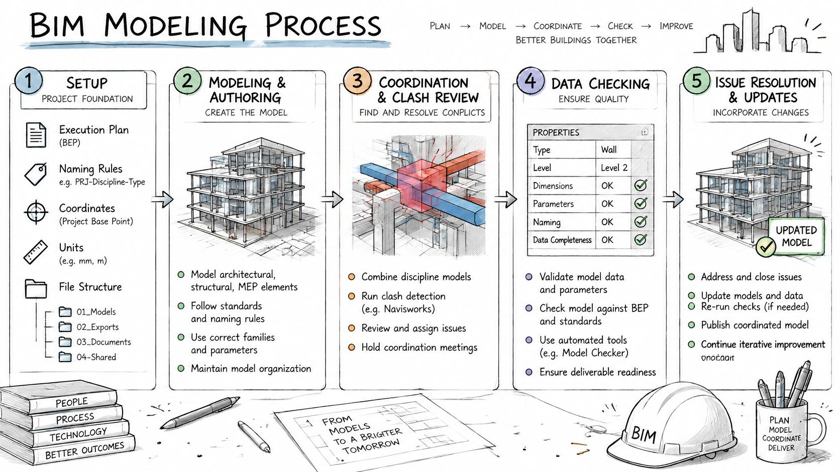
Start with a BIM execution plan, the working agreement describing what teams will produce and how they'll exchange it. Confirm naming conventions, imperial or metric units, coordinate references, file locations, and software versions. Test alignment using linked files before anyone invests substantial time in production.
Without that setup, a structural model may arrive rotated or displaced relative to the architecture. Correcting the view temporarily isn't enough. The team needs a repeatable positioning method so later exchanges don't recreate the problem.
The process moves from establishing shared rules to delivering information the next team can use.
Increase information as decisions become firmer
During schematic design, massing, spaces, and gross areas support layout and early budget decisions. Don't spend time modeling fastening details while the owner is still deciding the building footprint. At design development, replace provisional objects with typed walls, structural members, and main service routes so designers can evaluate how systems fit.
Construction documentation connects tagged elements to sheets and schedules. Review both outputs together, because a technically correct model can still produce an unreadable sheet or an incomplete schedule. Coordination should run alongside design, not wait until documentation is complete.
Procurement and fabrication require information suitable for the actual assembly being ordered or manufactured. A design model doesn't automatically meet that requirement. Confirm who develops shop-level content and who approves it before anyone uses it to order materials.
During construction, capture accepted changes and verify installed conditions before labeling the model as-built. Attach the asset information the owner will use, rather than delivering an unfiltered collection of product fields. Write these stages and acceptance points into the scope before modeling starts.
Levels of Development and How Much Detail to Model
A rooftop air handler can appear as a simple box early in design and as a detailed assembly later. Neither representation is wrong. The question is whether it supports the decision someone intends to make.
Level of Development, usually shortened to LOD, describes an agreed degree of element definition and reliability. Don't confuse it with visual complexity. A highly detailed downloaded family can still contain unverified dimensions or an unsuitable connection arrangement.
Level of Development reference by detail level
| LOD | Element reliability and detail | Typical use |
|---|---|---|
| LOD 100 | Conceptual representation or massing | Initial area and order-of-magnitude planning |
| LOD 200 | Approximate size, shape and location | Schematic layouts and preliminary space allowances |
| LOD 300 | Precise geometry, size and location as designed | Construction documentation and clash detection |
| LOD 350 | LOD 300 plus connections and interfaces with other systems | Coordination of supports, connections and clearances |
| LOD 400 | Fabrication and assembly detail | Manufacturing, assembly and installation planning |
| LOD 500 | Field-verified representation of installed conditions | As-built records and owner information |
Match reliability to the intended decision
Treat this table as a working reference, not a substitute for project-specific contractual definitions. State what each category must contain and what recipients may rely on. LOD is assigned to elements, so a project can contain well-developed structural framing alongside provisional equipment.
For the air handler, an approximate envelope can support an early rooftop layout and a preliminary allowance for the duct route below. It can't establish final curb dimensions or prove maintenance access. Those decisions require confirmed equipment information and explicitly modeled interfaces or clearance zones.
Likewise, an element's as-built status concerns verification, not decorative detail. Adding modeled screws doesn't make an unverified equipment location accurate.
Avoid false precision
Higher detail consumes authoring time, increases file size, and gives reviewers more information to inspect. It can also imply certainty that the design team hasn't earned. A precisely modeled connection may be mistaken for an approved fabrication detail when it's only a placeholder.
Model the information needed for the next authorized decision, not every detail the software can display.
In the execution plan, identify the required development by element category and project stage, including exceptions. Name which equipment remains provisional, who supplies final dimensions, and when replacement information is due. This gives the modeler a clear stopping point and protects downstream users from relying on unfinished content.
Model Uses in Coordination, Quantities and Scheduling
Model uses and the data each one depends on
| Model use | Data the model must carry | What goes wrong when it is missing |
|---|---|---|
| Clash detection | Consistent coordinates, discipline categories and element IDs | Clashes found on site instead of in the model |
| Quantity takeoff | Types, materials, assembly classes and gross and net rules | Quantities that cannot be reconciled to drawings |
| 4D scheduling | Phasing parameters and links to construction activities | Sequencing and logistics checks done by hand |
| 5D cost estimating | Classification codes and quantity-ready properties | Estimates rebuilt by hand from drawings |
| Facility handover | Asset tags, equipment data and as-built verification | Operators receive geometry without maintenance data |
Coordination requires issue resolution
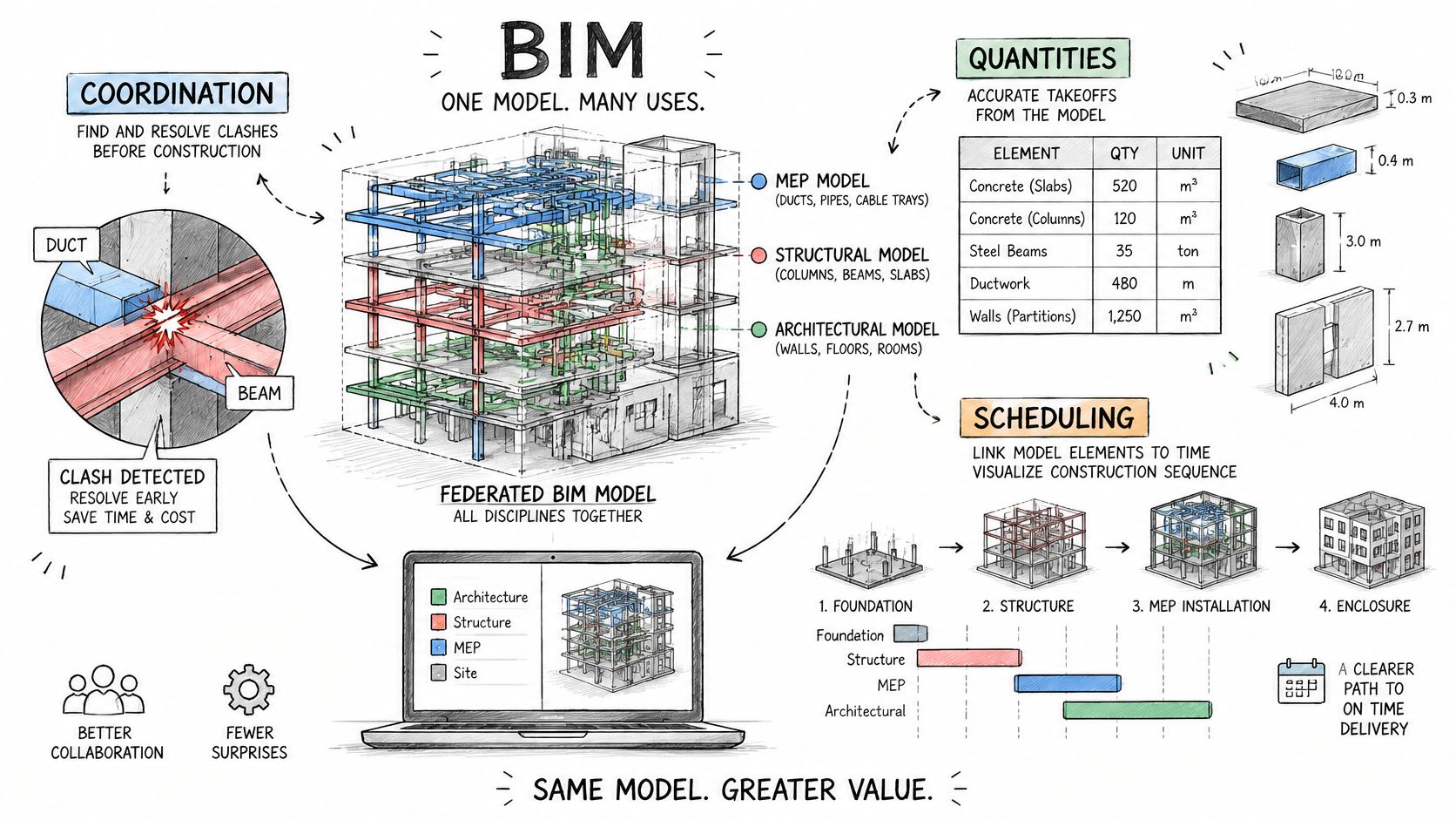
A federated model brings discipline models together for checking without requiring every author to work in the same file. The coordinator applies rules to identify hard clashes, such as a duct passing through a beam, clearance conflicts around equipment, and other rule-based issues.
A building case study using Revit and Navisworks identified 964 clashes, with conflict resolution associated with an estimated 41.7-day schedule reduction, according to the published coordination case study. That project-specific estimate illustrates the potential consequence of resolving conflicts before site work, not an expected saving for every building.
A clash count alone isn't a useful completion measure. Review severity, assign responsibility, and retest the revised elements. Duplicate intersections and intentional penetrations shouldn't distract the team from unresolved installation problems.
The coordination view helps reviewers understand where systems compete for space.
Quantities and downstream uses need different controls
For quantity takeoff, define whether each output represents gross, net, or installable scope. Document treatment of openings, waste, temporary works, and unmodeled components. Teams assigning quantity takeoff responsibilities should specify how model outputs will be reconciled against drawings and sampled field measurements.
Say a mechanical contractor models hangers as loose objects with no usable assembly classification. A takeoff filtered to the duct assembly may omit them even though they're visible. The problem is the extraction logic and object classification, not the appearance of the model.
4D scheduling links elements to construction activities so planners can examine sequence and logistics. 5D cost estimating connects measurable scope to cost information. Neither follows automatically from having geometry: planners need stable activity links, while estimators need classifications and agreed measurement rules.
Facility handover serves another recipient entirely. Operators need verified asset identifiers and equipment properties, not construction-only placeholders. For a first project, choose a limited set of model uses and list the information each requires before authoring begins.
Deliverables and IFC Exchange Formats
BIM deliverable formats and when to request them
| Format or file | Main purpose | Request it when |
|---|---|---|
| Native model (Revit .rvt) | Editing and authoring within one platform | Everyone works in the same software |
| IFC 2×3 | Neutral exchange in established workflows | A recipient's toolchain still reads this version |
| IFC 4.3 (ISO 16739-1:2024) | Current neutral exchange with broader content | The contract names the current IFC version |
| BCF | Issue records with viewpoints, status and responsibility | Clash and design issues must be tracked across teams |
| COBie | Structured facility data for operations | The owner requires asset information at handover |
| PDF and DWG sheets | Permit and construction drawings | The authority or contractor works from sheets |
Industry Foundation Classes, or IFC, is an open, vendor-neutral description of the built environment, not merely a container for shapes. buildingSMART's IFC documentation identifies IFC 4.3.2.0, commonly called IFC 4.3, as the latest official version, published as ISO 16739-1:2024. Established workflows may still require an earlier schema, so specify the recipient's requirement rather than assuming newer is automatically preferable.
A native authoring file supports continued editing within its platform. IFC supports exchange among organizations and tools. BCF carries issue information, while COBie organizes facility information for operations; neither replaces the authoring model.
Define a repeatable exchange test
Begin with representative elements rather than exporting an entire project and judging it from a screenshot. Include spaces, equipment, systems, and the quantities and properties the recipient needs. Make a controlled revision so you can check whether object identity and associated issue records remain usable.
Use this acceptance sequence:
- Export the named schema. Record the export configuration and the source model revision.
- Run schema validation. Use the buildingSMART IFC Validation Service and retain the result.
- Open the file independently. Inspect placement, units, spaces, systems, and required object properties in the receiving workflow.
- Compare critical information. Check selected quantities, classifications, and identifiers against the native model.
- Record exceptions. Assign responsibility for correction and identify anything the recipient must not rely on.
Keep technical validation separate from design approval
A passing validation result doesn't prove that equipment fits, that quantities cover the full scope, or that the building is constructible. Schema checks and project acceptance checks answer different questions.
Request a bundle containing the native model, exported IFC, validation result, and assumptions record. Include required sheet formats and facility information separately. Where an owner or authority specifies a particular submission format, confirm it against the contract documents and with the responsible design or compliance professionals before production starts.
Roles on a BIM Team and Coordination With Project Teams
The modeler authors and updates discipline content. The coordinator combines models, runs checks, and manages issue resolution. The BIM manager sets project standards and maintains the execution plan, although a smaller firm may combine these responsibilities in fewer people.
Design authority remains a separate responsibility. Architects and engineers make discipline design decisions; the contractor's BIM lead or preconstruction team uses the resulting information for planning, estimating, and fabrication coordination. Remote production support doesn't transfer professional approval authority.
Follow an issue through the team
Suppose a coordinator finds a duct intersecting a beam. The coordinator records the location and viewpoint, identifies the affected elements, and assigns the issue to the mechanical designer. The modeler shouldn't independently reroute the duct merely to clear the clash, because the change may affect system performance or other design requirements.
The designer approves a solution, the modeler implements it, and the coordinator retests the affected area. If structural changes are proposed, the structural designer joins the decision. A team evaluating MEP design coordination partners should establish that approval path before production begins.
The handoffs need to be visible to everyone involved.
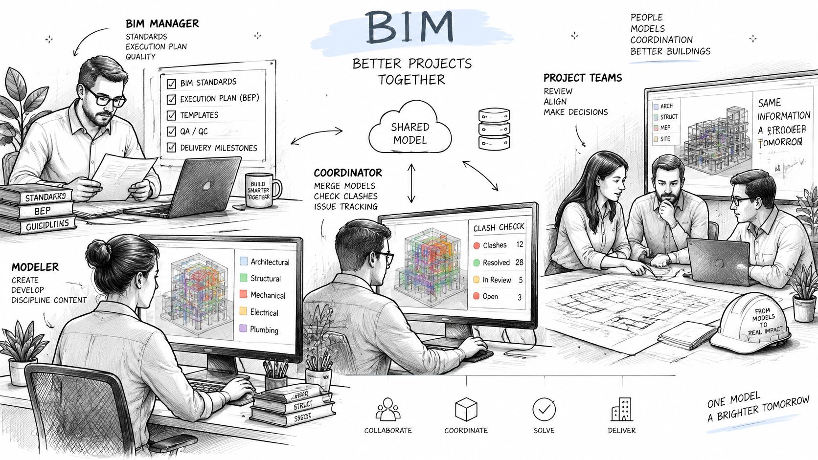
Make exchanges predictable
The National BIM Standard–United States material hosted by NIBS describes information-delivery processes in terms of when information is needed and what participating users must provide. Translate that principle into a working coordination rhythm:
- Model exchange. Publish agreed revisions to a controlled location on the scheduled exchange date.
- Clash review. Run documented tests with named tolerances and discipline pairs.
- Triage meeting. Separate design decisions from straightforward modeling corrections.
- Issue assignment. Record location, viewpoint, owner, status, due date, and required resolution.
Modelers working in Revit should demonstrate version fluency, family management, and disciplined parameter use. Coordinators using Navisworks should explain rule sets, tolerances, and how they group recurring issues. A BCF-capable issue tool can keep decisions attached to their spatial context.
Name the owner of each issue type in a responsibility matrix. A modeler working solely in a production capacity cannot approve code compliance; the appropriate licensed professionals retain responsibility for design and required sign-off.
Scope BIM Work and Its Limits Before You Assign It
Treating a model as coordinated because it looks complete is a costly mistake. Assuming an open standard guarantees clean exchange is another. Modeling every component at maximum detail adds a different problem: you pay for information the current stage may not need while making unfinished decisions look settled.
A study of BIM interoperability limitations identifies persistent export and import data loss, inconsistent identifiers, incomplete metadata mapping, and broken element GUIDs when models are reauthored. Open standards help teams communicate, but they don't eliminate the need to inspect whether the information retained its meaning.
Turn assumptions into scope requirements
Before assigning production, write a scoping brief that addresses these distinct requirements:
- Deliverable competency. Specify coordination-ready geometry, populated properties, a validated exchange, or handover information. Don't hide these different tasks under a generic modeling label.
- Element reliability. Assign development requirements by category and stage, with provisional items clearly identified.
- Exchange acceptance. Name the IFC schema, representative test content, and checks the receiving team will perform.
- Project conventions. Document coordinate references, naming, revision rules, file permissions, and software versions.
- Decision authority. Identify who approves design changes, resolves discipline conflicts, and provides required code sign-off.
Make the acceptance criteria observable. Instead of requiring a clean model, require named property fields, aligned links, traceable revisions, and resolved or explicitly accepted issues. Also name who corrects an exchange failure and who decides whether an exception is acceptable.
Acceptance question: Can the recipient use the delivered information for the named task, in the intended software, without undocumented repair?
Test the work before expanding the assignment
A useful screening exercise starts with an unfamiliar coordination model. Ask the candidate to interpret a controlled revision, implement it without disturbing unrelated content, and export the agreed exchange. Review both the result and the assumptions record, including how the candidate flags missing information.
For firms planning to hire remote BIM modelers, we provide modelers and coordinators through HireArchitects. Every candidate is interviewed, checked for English, and given a practical role test. Those tests include a takeoff for estimators, a markup set for draftspersons, and a design or documentation exercise for architects; your project-specific BIM exchange exercise should still reflect the actual assignment.
Remote staff also need controlled file access, suitable hardware, software licences, and working-hour overlap for coordination meetings. Most of our clients provide the software seat so project files remain in their systems. Agree who publishes models and who restores an earlier revision if a change fails review.
For renovation work, identify which existing conditions are verified and which remain assumptions. Don't ask a remote modeler to resolve uncertainty that requires a site inspection or a licensed design decision.
The Takeaway
BIM modeling is most useful when you treat the model as a database that must pass defined tests, not as a finished-looking 3D picture. Reliable outputs begin with decisions about purpose, element development, required properties, and exchange requirements. A successful export alone doesn't establish coordination or constructibility, and production staff don't replace professional design review.
For your next project, put the stage outputs into the scope and name the owner of each issue type. Set development requirements by element category, identify the required IFC schema, and prepare representative content for an exchange test. Keep provisional information visible so recipients know what they can safely use.
Then evaluate the work against its intended purpose: quantities that reconcile, issues that reach an authorized resolution, and delivered files that the receiving team can use. Written acceptance rules are easier to establish before production than to reconstruct after disciplines have developed incompatible files.
HireArchitects connects U.S. firms with remote BIM modelers and coordinators for architectural, structural, and MEP work. Visit HireArchitects to discuss your model uses, deliverables, and review responsibilities before selecting production support.